ECU: Install MTX Turbo ECU in a ATX Turbo 3S
After a ton of testing and countless hours beating my head on a table, I've finally finished experimentation with the TT ECU in my ATX TT conversion. And really, it's quite simple. The hardest part was figuring out what to do with the park/neutral position switch wire. After that the car ran miraculously.
I'm going to tell you exactly how you can put a TT ECU in your ATX car if you choose to do a TT conversion. This will allow you to run your conversion with only ONE oxygen sensor, without any wiring outside of the car (besides what it takes to extend your old sensor to the rear o2 housing)! Note that my conversion was for a 1G ATX car, and I used a 1G TT ECU. I see no reason why this can't work for later generations as long as you use the respective TT ECU for your generation and cut and splice the same wires I'm about to describe. But again, do this at your own risk if you are not a 1G! I'm not sure just how different the ECU pin assignments are between generations. However, I will name each pin so that you can cross-reference for yourself, and I'll also specify which pin designations are only for the TTs.
The following link to stealth316 will help you find out which wire is which: [1]. If you are not a 1G and wish to try this modification, your best bet is to research the difference between your current n/a harness and the TT ECU you are going to use in your conversion and make the same modifications I am about to describe.
- Buy a wiring harness adapter from here: [2]
- Find the pins on the TT ECU for the front and rear oxygen sensor, and the one wire on your n/a wiring harness for the rear oxygen sensor (for the 1G, this will be pins 55 for the front bank and 56 for the rear). Cut the wire designated for the front oxygen sensor and splice it in to the wire designated for the rear oxygen sensor. This allows you to simulate an o2 reading from both banks, even though you are really only getting a reading from the rear oxygen sensor!
- Cut the following wires:
- Reduce torque execution (pin 7 for 1G)
- Fuel Pump Relay 2 (pin 21 for 1G; this is a TT wire only)
- Active exhaust control unit (pin 102 for 1G; this is a TT wire only)
- Turbo wastegate solenoid valve (pin 105 for 1G; this is a TT wire only)
- Induction valve closed (pin 109 for 1G)
- Induction valve opened (pin 110 for 1G)
- Induction valve position sensor 1 (pin 111 for 1G)
- Reduce torque request 1 (pin 116 for 1G)
- Reduce torque request 2 (pin 59 for 1G)
- Starter relay signal, A/T only (pin 71 for 1G)
- It is imperative that you cut the starter relay signal wire! This wire goes into a pin in the TT ECU designated for a chassis ground, and you will short out that pin if you do not cut this wire! Note that I left the park/neutral position switch wire alone. This wire is now going into an input in the TT ECU designated for the starter relay signal. The car will still start as normal. Without the p/n position wire going into this input, the car will have very erratic timing when you shift into drive. I learned this the hard way, and it took me weeks to figure out the reason behind it.
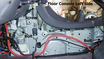
- Ground the wire for the chassis ground (pin 71 for 1G) coming out of the ECU side of your adapter. The best way to do this is to crimp male and female connectors on this wire and make an extention long enough to use the mounting point for the relay on the driver's side of your center console as a ground. The relay is the black box in this picture.

- Credit given to [www.stealth316.com] for the picture.
- Cap all of the wires you cut to ensure they don't short out on something, and install your wiring harness adapter and TT ECU. Then start it and be happy!
Hopefully this will be a great asset to you guys wanting to TT your ATX.
-BigTyla